Hey everyone. This is an update on how things are looking for the customs situation for certain LongMill orders coming into the US. Over the last few weeks, some LongMill shipments going to the US have been held at the border requiring customer SSN or TIN numbers to clear.
If you are in the US with a LongMill on the way, please read this post carefully.
This post is to inform everyone about the situation, what to expect, what to do, and what we’re working on to fix the process.
What is going on?
Due to changes in the shipping and customs processes implemented by the US Customs and Border Protection Services earlier this year, some shipments for the LongMill are getting held up at the border.
Why are shipments getting held up?
There are currently two main reasons why shipments are getting held up.
First is the high-value nature of some of the shipments containing LongMills. This article (https://help.cbp.gov/s/article/Article-314?language=en_US) contains information about the clearance of shipments. While we continue to cover the cost of duties and taxes directly, customers still need to provide this information.
Second is the implementation of Section 301 Articles of China. While most of our products are made in Canada, some items are made in China. There is currently a trade war between China and the US, which means that the US will identify and apply duties to Chinese-origin items separately. This means that these parts are more likely to get flagged as well. We automatically provide the correct data for customs services, but sometimes this can require additional processing to complete.
Alternatively, you can send us an email or contact us with your details directly and we will forward them to the right place.
If you see that your item is in the warehouse, please contact us ASAP.
If we don’t receive a response within 10 days, we may need to re-ship your items.
What else are we doing to address this?
There are currently several things we are doing to reduce the friction in sending orders to the US. Some of these we are implementing right away, while some things are longer-term plans that may take several weeks or months. These include:
Updating our customs form to provide more information and mitigate the chances that the order will be held up at the border.
Proactively contacting customers and placing notices for people to follow to get additional information
Creating a US entity/corporation to help assist with the transfer of goods between the US and Canada
Establishing a system for communication between us and customs clearance to provide the information more quickly.
With over 60 shipments currently affected, we are working on this as quickly as possible. However, in the meantime, it is likely we will need the co-operation of our customers to help work with customs to get everyone’s orders to them!
We’ve recently experienced some of our customers having their machine orders held up at US customs. For some orders above the value of $2500USD, UPS is requesting customer tax information for clearance. We are working on eliminating this process, but either UPS or Sienci Labs may reach out to you for the extra info. Some changes to our customs documentation implemented in the last few days should mostly eliminate this issue, and we are working on automating a system to let customers that fall under this specific set of rules (US customers with high-value shipments) about the situation proactively. Currently, this has affected about 10-12 customers in the past few weeks, which is a small percentage of the overall number of issues, but we just want to let everyone know just in case this happens to you.
Please note that this DOES NOT mean you will need to pay duties and taxes, but it does mean that we may be charged warehousing fees if the item sits in storage for too long.
LongMill and Extension Kit Orders
We have raised lead times for LongMill orders as we currently have a large queue. We are consistently shipping out machines on a daily basis, but due to a big increase in sales this month, we are currently at full capacity. By next week, we will have another three new hires to assist with packing and assembly, which should bring down our lead times. Additionally, we are currently working on acquiring additional production space to relocate our rail processing and create additional inventory storage space.
We are also actively working on Batch 8 supply chain. Based on current sales numbers, we expect to start Batch 8 in around May or June. This is quite a lot sooner that expected. Although many of the key components for the LongMill have been ordered, due to the long lead times we face for some of the parts, we expect that there will be longer lead times closer to the transition point in Batch 8.
LaserBeam
Due to a shortage of some components, we have raised lead times for the LaserBeam. However, most customers may have gotten theirs a lot earlier. As our typical fashion, we want to provide conservative lead times. We have partially restocked all of the parts, which means that we are currently working through the assembly for the remaining orders in the queue, and expect to wrap up pending orders by end of next week. For new orders placed now, we’re telling customers that they may need to wait up to 6 weeks potentially, but it’s likely most will ship sooner.
We’ve made some design changes on the heatsink and wiring that we’ve started implementing, which will reduce assembly times so that we can produce these items faster.
Additional parts for the LaserBeam are expected to arrive around the start of March, at which point, we can pre-assemble and keep inventory on hand for Lasers.
The engineering team has continued to work on the rotary axis kit. Here are a couple of updates.
We received a sample rotary axis a couple of weeks ago which we have been using for testing. Due to some imperfections, we have been reconsidering our strategy for the production of the rotary axis. Initially, we were planning on using off-the-shelf components for the whole kit, doing QA testing, and shipping to customers, but as we have continued to do testing and research, we have started to reconsider and look at custom designing and making some or all of the rotary axis from scratch.
There are a few areas that must be improved to reach large-scale production, especially in the quality and tolerances of the components that off-the-shelf rotary kits have shown to be inconsistent. First is the edges of the bottom of the rotary axis, which need to be accurate to allow it to mount and align with the track accurately. Second is the motor mounting plate, which needs to line up with the rotary pulley. And lastly, the overall fit and finish need to be consistent and of good quality. We found that from the sample, these were notable areas that needed improvement.
When we started manufacturing LongMills, we used many off-the-shelf components as they were the most affordable at a small scale. However, as time has gone on, basically all LongMill components are toleranced and custom-made to our specific requirements, even if they are otherwise exactly the same as an off-the-shelf alternative. At scale, quality issues compound, and making custom, higher-quality parts helps mitigate issues and ensure fewer issues with assembly and use.
I share the same sentiment with the development and production of the rotary axis. For it to be a viable product, we need to produce hundreds (and eventually thousands) of kits. To accomplish this, we need to take control of the whole production process.
At this stage, we are currently deciding how we want to progress with the production of the rotary axis. We are doing a cost-benefit analysis and working on design ideas. As far as where we are with things now, for us to bring up quality, we also need to bring up the price. Based on our survey results, it seems like interested customers are able to accommodate some increase in price, given that we can provide more value for their rotary axis. It seems like increasing the price and budget of the project will overall provide more value, as we can dedicate more to the software, hardware, and resources for the rotary axis.
The software team is also currently working on the implementation of 4th-axis support in gSender. Some things in consideration include:
Visualization of rotary axis code
Switching between both modes
Homing and zeroing of the rotary axis
Firmware and control board changes
The engineering team has currently made tons of progress overall with regard to documentation and processes that will eventually be used with whichever rotary axis we will provide.
At this stage, we do not have exact dates on when the rotary axis will be launched, but we expect the earliest time for it to ship to be in late summer. If you’re interested in the project, I encourage you to stay in the loop on our blog and social media.
Happy New Year all. It’s been quite a year in 2022. Here are a couple of milestones we’ve hit in the past year.
This post was originally shared in our internal company newsletter.
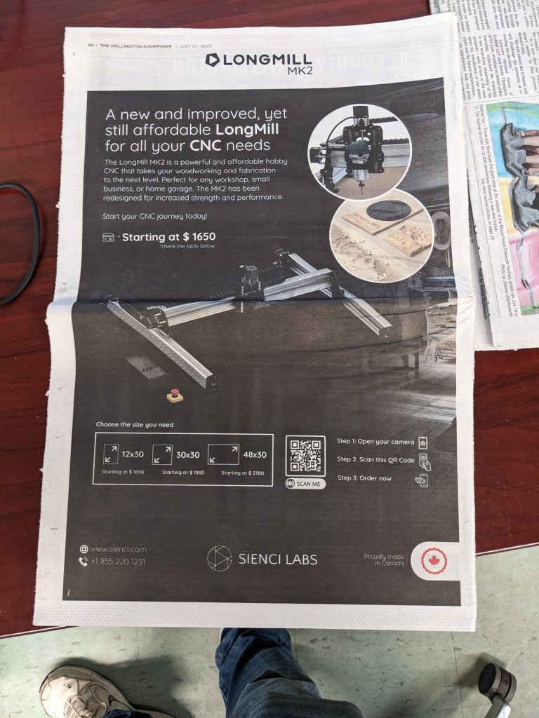
Launch of the LongMill MK2
In early 2022, we launched the LongMill MK2, the successor to the LongMill MK1. This was a big milestone for us as the LongMill MK2 was a culmination of learning and experience in two years of shipping the LongMill MK1.
Also with the LongMill MK2, we introduced a new size, the 48×30. This new size allows for the use of full 4ft wide sheets. It is now the most popular variation of the LongMill.
Chris and I are happy to say that the launch of the MK2, albeit with some hurdles, went smoothly, with our resource development and customer service teams handling these areas amazingly well.
Launch of the AutoZero Touchplate
Our launch of the Autozero touchplate is a major milestone in the hobby CNC industry as the first to allow for zeroing straight and irregularly sized bits. This project took a lot of time to develop, especially in the manufacturing side. To date, we’ve sold close to 1000 units, and this continues to eclipse the original touch plate in sales.
gSender development
gSender, first launched in closed Alpha in early 2021, has now gone through 10 iterations through 2022. This is an insane pace of development, with a new version almost every month. Some new features implemented this past year include:
Improvements to the surfacing tool, such as adding zig-zag pattern and overall stability
Addition of machine profiles outside of the LongMill ecosystem
We now have further established our health and safety at Sienci Labs. Thanks to Kelsey, John, Mike, Steph, and the rest of the operations team, we now have stuff like training videos, first aid, WSIB certification, eye wash stations, and properly stocked first aid kits.
SR&ED
Thanks to Kelsey, we made our first filings for SR&ED in 2022. This means we are able to receive nearly $300,000 in tax credits to apply against the corporate taxes. While the engineers aren’t thrilled to do the paperwork needed to make the claims, it does cover a substantial amount of our R&D costs.
We expect to make a new filing for 2023 covering additional developments for items such as the laser, rotary axis, and control board development.
Team growth
2022 is also highlighted by a big jump in the size of our team. In 2022, 10 new employees joined our team, with most new members being in engineering, software development, and marketing. Given we were about 19 people strong at the start of 2022, this means we had a 52% growth in our team.
2021 was an extreme growth year, with our revenues growing by 75.5%. This made put a lot of stress on our team as we received way more traffic than we expected. 2022 was a year of establishing our team. By bringing on new talent, we were able to streamline and improve many aspects of the company, such as inventory management, customer service, marketing, and resource development.
Revenue growth
While smaller than the spectacular 75.5% revenue growth in 2021, we still saw a respectable 34.7% in revenue growth. We saw a big jump in revenue in software and add-ons sales, as we grew our offerings in those areas.
The start of 2022 was quite slow, partially due to economic factors and issues with our supply chain causing lead times to extend and cause delays. Despite these issues, once we had them resolved, we’ve reached record sales at the end of the year, October to December being the highest in sales we’ve seen in company history and exceeding my initial projections.
Operational Improvements
There have been many improvements to operations. Some notable ones include:
USMCA certification: By creating USMCA certification, we’ve eliminated a large of taxes being paid when LongMills and other Canadian-made products cross the border. Those working in customer service would have been familiar with issues arising when folks needed to pay for duties and taxes, which this new certification eliminates.
Improved QA processes: Thanks to Mike and Jon, as well as the other engineers, nearly all components now have QA processes and documentation. This has greatly eliminated having to ship out missing parts and overall improved the quality and performance of the LongMill. Employees can now use tablets, calipers, gauges, and other tools to collect more data and improve the quality of our parts.
Katana to Batching system: Kye and the rest of the operations team spent a lot of time in 2022 establishing a new inventory system. Initially, we were using ATUM, which worked for the most part but introduced instability in the website. Katana took inventory management a step further, but the work order system met resistance with the packing staff. We learned that with the high level of experience our packing staff had, work order systems aren’t as critical. We have now since doubled down on the batching system that was originally implemented in the inception of the company.
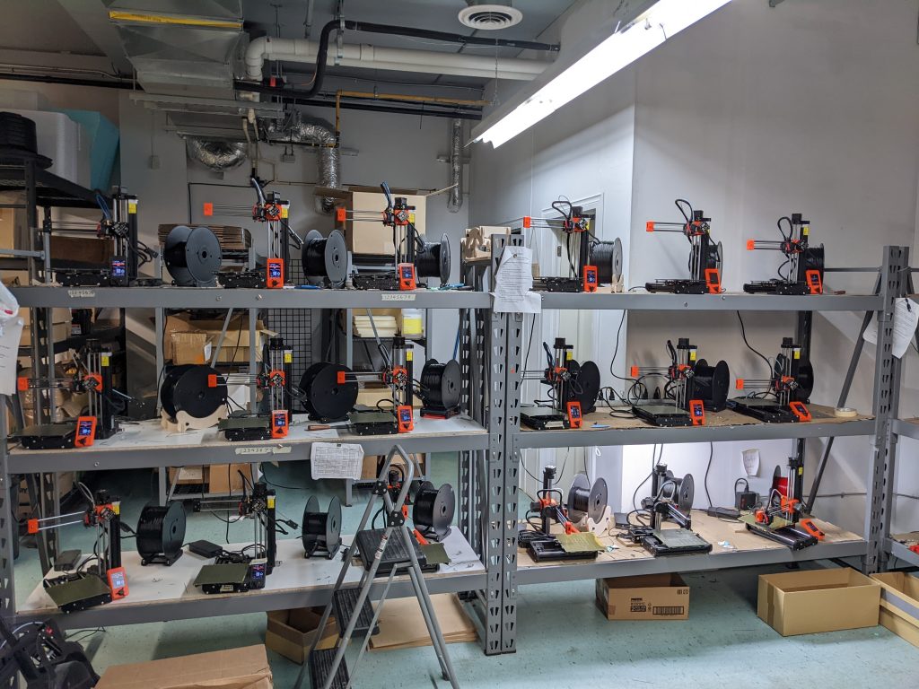
Improvements to the 3D printing farm: 2022 brought a number of improvements to the print farm. While the Ender 3s were good in the way that they were cheap and easy to come by, at scale, the overall improvement to the print consistency and features like auto bed leveling and filament run-out sensors of the Prusa printers turned out to be worth the extra cost. Also, with the implementation of the Kanban system turned out to streamline the inventory tracking process as well.
Ron has also been implementing improvements using his CAD skills, making brackets to hold power supplies and USB cables, further optimizing the farm.
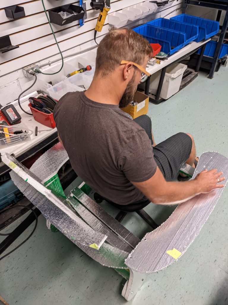
Extrusion saw and tapping arm: Given that the cost to have extrusions cut and tapped out of house would have been around $30,000 per batch of around 500 units, it made a lot of sense to bring it in-house. I’m very proud of the purchase of our sub $2000 extrusion saw as well as the tapping arm system that Mike, Jon, Dylan, and Nini has put together to make this process cheaper, faster, and easier.
Workshop improvements: We’ve brought in a lot of new tools and equipment in 2022, especially with Adam’s organizational skills and Mike’s retail therapy. Our workshop started off as a mess but has now been better tamed, with easier access to working CNC machines and tools.
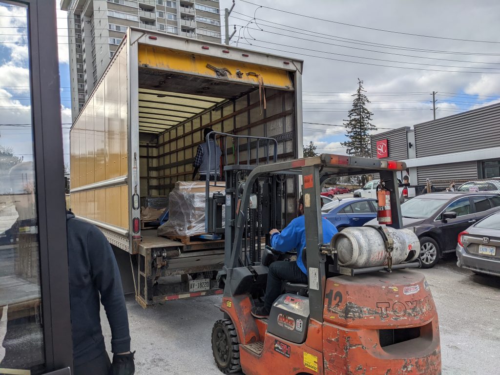
Forklift: We held out on getting a forklift by using liftgates and other lifting contraptions, but the propane forklift was ultimately a great investment. With the new sea cans, growing amount of inventory being transported, and the cost of using a liftgate, we now use the forklift all of the time. It’s also important to share that we now have several staff now certified to drive the forklift.
Marketing and content creation
One of the largest areas of growth in our team is with our marketing and content creation team. With over half of our customers coming from Youtube, one big focus was in content creation. And with all the hard work, you can see we’ve greatly increased the number of engagements in our Youtube channel. Other marketing and content creation achievements include:
Establishment of our weekly contests
Improvements and optimizations to our Google and Facebook Ads
Improvements to our file management systems and use of NAS
A Sienci Tik Tok
Regular LaserBeam podcasts
Way better lighting in our videos
and more…
Filming bootcamp
Looking forward in 2023
2023 will be a year of innovation. I say this as our engineering and software development team continues to push out new products and developments which will play a significant impact in the establishment of the hobby CNC industry. Some developments include:
A new, smarter CNC control board
Continued developments and features in gSender
Rotary Axis
Continued development in the LaserBeam
Improvements to the mechanical components, such as the couplers and locking nuts on the LongMill MK2
Additional potential developments on the horizon include:
A new router/spindle system
New, unique end mills and bits
Heavy duty Z axis and other mechanical improvements to the LongMill
AltMill and YesHappy development
Plasma CNC development
First iterations of our new control board
Additionally, we expect to continue putting out more educational content and tutorials for our products. These include project videos, livestreams, and resource videos. This is expected to increase sales, as more than half of our customers find out about us through Youtube, but also bring more value to our community as we create useful content for the public to help them learn how to use our products.
As our company continues to grow and scale, it’s important to acknowledge the changes to Chris and my role in the company as well. I am grateful to have talented and hard-working people surrounding us to continue to push our company forward and take on many of the responsibilities that we previously handled. This has given us more freedom and satisfaction in our personal lives because of the talents of our staff.
Thank you to everyone who was part of our 2022, and we look forward to continuing our journey in 2023.
What do you want to see in 2023? Did I miss anything for 2022? Let me know!
LongMill and Extension Kits are shipping on schedule. There is currently a large queue of orders, so we expect new orders to ship in around 3 weeks. We were expecting to have shorter lead times at the end of December, but due to a high number of orders, we’ve kept our lead times to 3-4 weeks.
We are currently in the process of bringing on 1-2 additional packing and assembly staff as some members are moving into customer support roles. We expect having a few new members on the team will help keep pace with the new sales as well as for future products.
We are expecting our queue to take about 2 weeks to clear and lead times to come down to around 2-3 weeks around the end of January.
LaserBeam Orders
We are currently waiting on a new batch of fans, bodies, and heatsinks for the LaserBeam. These parts are expected to arrive in the next few weeks. Some orders will ship earlier than scheduled with currently available stock, but customers are advised that some orders may take 4-6 weeks to fill based on part availability.
Hey there! I hope its been a wonderful year for everyone. Please note that our offices will be closed for the holidays from Dec 24, 2022 to Jan 2, 2023. We will reopen for regular business on Jan 3rd.
Some of our staff may be around to a limited degree to tie up some loose ends and receive incoming shipments, but most of the team will be on vacation during this time.
Shipping and support may be limited during this time.
Support
Support through our contact form and phones will be limited during this time. If you are looking for help with something, please see our FAQ (sienci.com/faq/) or resources page (resources.sienci.com). If you can’t find an answer on our website please submit a ticket on our Contact Us page. We will reply back to your messages when we return from holidays.
Shipping
Shipping of orders may be limited during this time. If your order has not shipped yet or you place an order during the holidays, it will ship after we return.
The business directory at https://business.sienci.com/ has now been sunset. Users will soon no longer be able to access this page (if it hasn’t already been shut down).
The goal of this directory was to help connect LongMill users and members of the public looking for custom CNC services. However, due to the lack of engagement, I have decided to shut the page down.
Looking to connect with other CNC users still? Please check out our forum post “Where is everyone from?”.
I’m excited to share that new macros for the AutoZero Touch Plate can now be found in our resources! This means that users who wish to use the Autozero Touch Plate with gcode senders that are not gSender can now do so with senders such as UGS, CNCjs, and Buildbotics/Linux CNC controllers.
We hope that users outside of the LongMill ecosystem will be able to use our unique touch plate for their CNCing.
For folks not familiar, the AutoZero Touch Plate is a revolutionary CNC touch plate design that allows for homing of both straight and irregularly shaped bits (v-bits, ball nose, and tapered) in the X, Y, and Z directions automatically using a unique chamfered-edge design.
Unlike most conventional touch plates, AutoZero also automatically measures and calculates the size and position of the bit that you’re using, allowing users to skip the process of measuring and inputting their tooling sizes into the software. Plus, with our gSender control software, users can use pre-built settings to have a seamless experience homing bits on their CNC machines.
One of the common asks that users have been requesting has been adding a 4th axis or rotary axis to the LongMill. We’re now happy to share some of the work we’ve been doing to add this support to the machine. We are currently in the early stages of development for this addition but have been able to get some good results from our testing.
A survey can be found at the end of the article, where you can help us understand your needs and get feedback and comments if you wish to participate!
Although things are not finalized yet, here’s a breakdown of a rotary axis kit we’re looking to develop for the LongMill. Our goal is to have a kit that allows for a plug-and-play addition of a 4th axis to any LongMill.
Motorized chuck and headstock, along with a mounting solution to the machine
Cables and switches for connecting to the LongBoard controller
Resources and customer support to help set up and use the kit
What is a 4th axis?
Most CNC routers like the LongMill use a 3-axis system, which consists of a X, Y, and Z linear motion system that is used to position bits and end mills. One of the limitations of a 3-axis system is the fact that 3-axis machines cannot make “undercuts” without flipping or material manually. Since the machine only can orient the bit vertically, there are limitations to the types of geometry it can carve.
To address these limitations, CNC machines can come with additional degrees of motion, typically including a 4th or even 5th axis. In the case for the LongMill, a rotary axis positioned along the X direction allows the machine to turn a part as the X and Z axis can move in sync as the material turns and rotates.
On a mechanical level, the 4th axis for the LongMill will come with a chuck to hold material as well as a series of bearings and pulleys connected to a stepper motor to rotate the material as the machine carves.
What can it be used for?
The best way to think about 4th axis is to look at it as a computer-controlled lathe. Projects that are best suited for using a 4th-axis include making table legs, chess pieces, threads, and other mostly cylindrical objects.
Who is it for?
At this current time, we are exploring the suitability of a rotary axis as examples of practical use are limited on the market. We’ve put a link to a survey at the end of the article to help us understand the use cases of a rotary axis by asking what the community is interested in creating!
Based on our research and experience, we feel that this is best suited for early adopters and people who are wanting to tinker with the technology and can accept that at this current time, it is quite primitive. There are quite a few steps to using this add-on and the learning curve involved that may not be intuitive to folks that are mostly familiar with the typical cartesian coordinate system. Additionally, there are a lot of new software features that need to be tested and created, and we expect software bugs in the initial development of the rotary axis that may be frustrating if it’s not expected in the early stages of this product.
Limitations
Software
By far the most important aspect of the viability of this project comes down to the software since a rotary axis is useless without being able to program it. At the current time, the number of software that supports 4th axis machining is limited and the ones that we feel are best suited for this application are paid. Some options include:
Vectric VCarve Desktop, VCarve Pro, and Aspire ($349USD, $699USD, $1995USD)
Fusion 360 ($1600/year)
DeskProto Multi-Axis Edition (€249.00 for the hobbyist edition, €995.00 for commercial)
From our testing, Vectric’s software, in terms of functionality, ease of use, and price, is our recommended choice.
We won’t get into any specific details comparing the software today, but it’s likely that when we start to create documentation for 4th-axis programming, that it’ll be done using Vectric software.
Electronics
It’s also important to specify that with the current setup, this is not a true 4th axis. Rather, this setup uses the motor control from the Y-axis, disabling the linear motion from the two motors and redirecting the power to a single motor that controls the rotary axis. At this current stage, the plan is to provide hardware that allows for switching between rotary and linear motion by connecting directly to the control board.
While this seems like a big downside because the programming of true 4th axis is quite complicated and not supported by most hobby-level software.
Users who wish to explore true 4th-axis machining will need to use a more advanced control system and sending program to control the extra axis. We are working on creating electronics and software that will support this in the future, but we are not quite ready to share these details yet.
Hardware
Due to the size of the LongMill and the size of the rotary axis, users should expect to be able to cut materials up to 4.5 inches in diameter and roughly 10 inches less than the length of their X-axis. So 12×30 and 30×30 users would be able to do up to 20 inches in length and 48×30 users would be able to cut up to 38 inches in length.
The longer the material, the less stable the cutting is, since the material is only supported from each end of the machine with a chuck and headstock. Further testing will show practical speeds and feeds at different sizes.
Pricepoint
During the development of the project, we explored using either an off-the-shelf rotary axis option or designing one from scratch. It turned out that at this stage, it would be difficult to beat the cost of an off-the-shelf option purchased in bulk since if we were to design and manufacture it ourselves, the investment into design and the high volume of custom parts we’d need to produce would make it economically unviable.
Additionally, the off-the-shelf option appears to be quite well-made and good value, and ubiquitous enough that customers on a budget and willing to tinker may be able to source the same or similar option and use it for their machine, rather than buying it straight from us.
We’re estimating a landed unit cost for a pre-made unit in bulk will cost around $200. Additionally, the cables and electronic hardware required would add roughly another $15-20 to the unit cost. We also may need a precision fixturing plate that may cost around $100. Once applying a margin to account for things like development cost, customer support, shipping, resources, packaging, quality control, and everything else that we need to run a business, we’d estimate a price of around $500-700CAD per unit.
Additionally, users should budget to purchase software, as at this time we do not have a recommended free software option.
Next steps
Our next step is to determine the demand and viability of providing a rotary axis option to our user base. If we see enough demand, we can start to invest more time and resources in additional work and development such as:
Sourcing parts to create a rotary axis kit
Developing new features into gSender to add 4th-axis compatibility
Design of hardware for mounting to the machine
Resource development
Stress and long-term testing
Our first step is to share this survey so that interested LongMill users can share their thoughts, wants, and opinions on what they want to see in a kit.
In terms of timeline, we expect to make decisions on the direction of this project by the end of January. Depending on demand, we’ll start taking pre-orders for the kit and start sourcing components. We expect the sourcing and manufacturing process to take around 2-3 months, which brings us to around April-May 2023 when users may start getting their rotary axis kits.
Survey
To participate in the survey, please click the link below. Your participation is greatly appreciated!
Using a new feature in our e-commerce sales tracking software, we can now look at all of our customers on a heatmap!
Here are some cool facts:
We have customers in 59 countries, including Aruba, the Faroe Islands, and Oman!
The United States represents our largest demographic, followed by Canada. We have customers in all 50 States!
We estimate that we have about 5000-6000 LongMill users in total!
LongMill and Extension Kit Orders
Last month we slowed down shipping due to a shortage of lead screws and linear guides. I’m happy to say that our new batch was expedited (at no small cost) and we are currently working to get through the current backlog. Although we expect to get through most of the backlog next week, we are currently keeping our 3-4 week lead time for the time being. Once the backlog is cleared orders should ship within 1-2 weeks. We will have an updated lead time once we have gone through initial quality checks today and early next week for the new batch of parts.
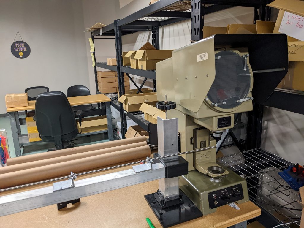
Batch 6, which consists of 1500 machines, is officially complete! New orders are now part of Batch 7. For changes and improvements we’ve made through Batch 6, check out the write-up from the last production update. Batch 7 consists of another 1500 LongMills.
Recently we had a few issues with bent lead screws. We’re currently working on testing all of them before shipping to make sure they are straight and don’t cause binding issues. Here we’re using an optical comparator to check how much deviation each screw has.
LaserBeam Orders
Orders for LaserBeams continue to ship as usual with fairly short lead times. Although we have stock, we are currently working on adding another 500 units to inventory. Due to a sudden increase in sales, we are currently low in stock and while some order will ship quickly, customers should expect to wait 4-6 weeks for their orders to ship based on part availability.
End-of-Year Holidays
As we typically do, we are on closing for holidays from Dec 23rd to Jan 2nd. If you have any questions or need anything shipped out, please reach out to us before the 23rd. There may be some of us providing limited holiday support and getting ready for the new year, but the large majority of us will be on holiday.
Happy Monday folks. Over the last couple of weeks, our engineering team has been working on creating a standardized testing method and recording values to provide recommended feeds and speeds for a large number of end mills that we provide in our store.


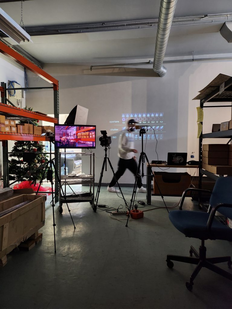 Filming bootcamp
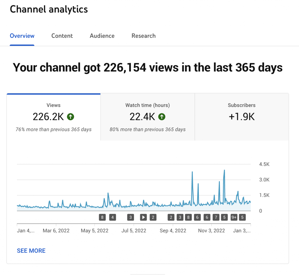
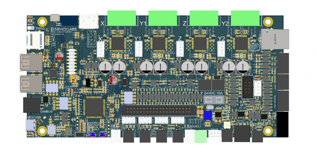 First iterations of our new control board


